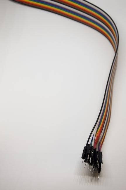
An electric bike wiring diagram is a visual guide that illustrates the connections between components like the controller, motor, battery, and throttle. It helps users understand how to properly connect circuits, ensuring safety and optimal performance. These diagrams are essential for both novices and experienced riders, providing a clear roadmap for troubleshooting and customizing e-bike systems.

Understanding the Components of an Electric Bike Wiring Diagram
A wiring diagram details the connections between key components like the controller, battery, motor, throttle, and brakes. It illustrates how these parts interact, ensuring proper installation and troubleshooting.
Controller and Its Role
The controller acts as the brain of an electric bike, managing power flow between the battery and motor. It receives input from the throttle and brake systems, regulating speed and torque. Modern controllers often include features like regenerative braking and customizable settings. Proper wiring ensures smooth communication between components, preventing overheating or malfunction. The controller’s role is crucial for efficiency, safety, and overall performance, making it a focal point in any wiring diagram.
Battery and Motor Connections
The battery and motor are central to an electric bike’s operation, requiring precise connections. The battery supplies power, while the motor converts it into motion. Wiring diagrams detail how to connect these components safely, ensuring correct voltage and current flow. Proper connections prevent overheating and prolong component life. The diagram outlines positive and negative terminals, highlighting essential safety measures like fuses and circuit breakers; Understanding these connections is vital for maintaining efficiency and reliability in the e-bike system.
Throttle and Brake Systems
The throttle and brake systems are crucial for controlling an electric bike’s speed and safety. The throttle connects to the controller, regulating power delivery to the motor. Brake systems, including regenerative braking, interact with the controller to cut power or capture energy. Proper wiring ensures smooth acceleration and reliable braking. Diagrams detail connector types and wiring colors for these components. Correct installation prevents sudden acceleration or brake failure, ensuring rider safety. Understanding these connections is vital for maintaining control and safety while riding.
Key Elements of a Wiring Diagram
A wiring diagram includes power supply connections, circuit designs, and component links; Color-coded wires and symbols simplify identification. Safety features like fuses and circuit breakers are highlighted.

Power Supply and Circuit Design
Power supply and circuit design are crucial in an electric bike wiring diagram. They outline how the battery connects to the motor and controller, ensuring efficient energy flow. Proper circuit design prevents overloading and short circuits, while color-coded wires simplify identification; Safety features like fuses and circuit breakers protect the system from damage. A well-designed power supply ensures consistent voltage and current delivery, optimizing motor performance and battery life. Understanding these elements helps riders maintain and troubleshoot their e-bike effectively, ensuring reliability and safety on the road.
Motor Speed Control

Motor speed control is a critical aspect of an electric bike wiring diagram, as it determines how power is delivered to the motor. The controller acts as the brain, regulating the motor’s speed based on throttle input. Proper wiring ensures smooth acceleration and maintains optimal performance. The diagram illustrates how the controller connects to the motor, throttle, and battery, ensuring precise control. Safety features like overcurrent protection and thermal monitoring are also integrated. Understanding this section helps riders customize their e-bike’s performance, such as adjusting speed limits or torque output. A well-designed motor speed control system enhances ride quality, efficiency, and overall safety, making it essential for both DIY enthusiasts and experienced technicians.

Safety Features and Protections
Safety features and protections are integral to any electric bike wiring diagram, ensuring the system operates reliably and prevents hazards. Overcurrent protection, such as fuses or circuit breakers, safeguards against electrical overloads. Thermal monitoring prevents overheating by regulating motor and controller temperatures. Proper insulation and grounding of wires are critical to avoid short circuits and electrical shocks; The diagram highlights these protections, detailing how components like fuses, voltage regulators, and emergency cutoffs are integrated. By following the wiring diagram, users can ensure their e-bike meets safety standards, reducing the risk of malfunctions or accidents. These features are essential for maintaining rider safety and extending the lifespan of the electrical system.

How to Read and Interpret a Wiring Diagram
Reading an electric bike wiring diagram involves identifying symbols, understanding connectors, and following the flow of power and signals. Use color codes and labels to trace connections.
Identifying Symbols and Labels
In an electric bike wiring diagram, symbols represent components like controllers, motors, and batteries. Labels clarify connections, ensuring wires are linked correctly. Common symbols include circles for connectors and lines for wires. Labels like “TH” for throttle and “BRK” for brakes help identify functions. Color codes on wires (e.g., red for positive, black for negative) are crucial for tracing circuits. Understanding these symbols and labels is key to interpreting the diagram accurately. Always cross-reference with the provided legend or guide for clarity. Proper identification ensures safe and efficient wiring, avoiding short circuits or component damage. This step is foundational for troubleshooting and customizing your e-bike system effectively.
Understanding Color Codes
Color codes in electric bike wiring diagrams are essential for identifying wire functions. Red typically indicates positive connections, while black signifies negative or ground wires. Other colors like yellow, blue, or green may represent specific functions such as throttle signals or brake inputs. These codes help users trace circuits and connect components accurately. Consistency in color coding ensures safety and prevents wiring errors. Always refer to the diagram’s legend to confirm color meanings, as standards may vary. Proper understanding of color codes simplifies troubleshooting and customizing your e-bike’s electrical system. This step is crucial for maintaining reliability and performance in your electric bike’s wiring setup.

Troubleshooting Common Issues
Faulty connections, blown fuses, or a non-responsive throttle are common issues. Use the wiring diagram to identify and test components like the battery, motor, and controller. Ensure proper voltage and continuity for reliable operation.
Diagnosing Faults in the Wiring

Diagnosing faults in an electric bike’s wiring requires a systematic approach using the wiring diagram. Start by identifying symptoms, such as a non-responsive throttle or motor. Use a multimeter to check for continuity and voltage drops in key connections. Look for signs of short circuits, blown fuses, or loose terminals. Refer to the wiring diagram to trace connections between components like the controller, battery, and motor. Test individual circuits to isolate the issue. Common faults include faulty hall sensors, incorrect throttle wiring, or misconnected brake levers. Always ensure the diagram matches your e-bike’s specific configuration. By methodically testing each component, you can pinpoint and resolve wiring issues efficiently, ensuring safe and reliable operation of your electric bike.
Testing Connections and Components
Testing connections and components is crucial for ensuring the reliability and safety of your electric bike. Start by using a multimeter to check voltage and continuity across key points in the wiring diagram. Verify that the battery voltage matches the system’s specifications and that there are no unexpected drops. Test the throttle and brake sensors to ensure they provide accurate signals to the controller. Inspect all connectors for looseness or corrosion, as these are common failure points. Use the wiring diagram to trace and verify each connection, ensuring proper polarity and wiring configuration. If a component fails testing, refer to the diagram to identify its location and replace it as needed. Regular testing helps prevent electrical issues and ensures your e-bike operates smoothly and safely.
Electric bike wiring diagrams are essential tools for understanding and maintaining your e-bike’s electrical system. They provide a clear visual representation of how components like the controller, motor, battery, and throttle connect and function. By following these diagrams, riders can ensure safety, efficiency, and proper functioning of their e-bikes. Regular inspections and updates to the wiring system, guided by these diagrams, help prevent electrical issues and extend the lifespan of the bike. Whether you’re a professional mechanic or a DIY enthusiast, mastering the wiring diagram is key to optimizing performance and troubleshooting effectively. Always refer to the diagram for guidance, as it serves as the backbone for maintaining and upgrading your electric bike.